| The Hindenburg |
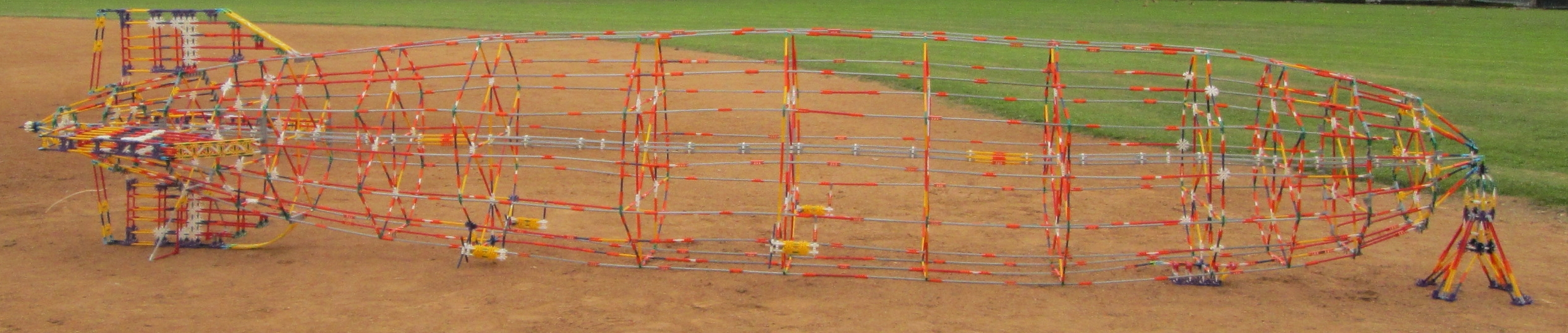
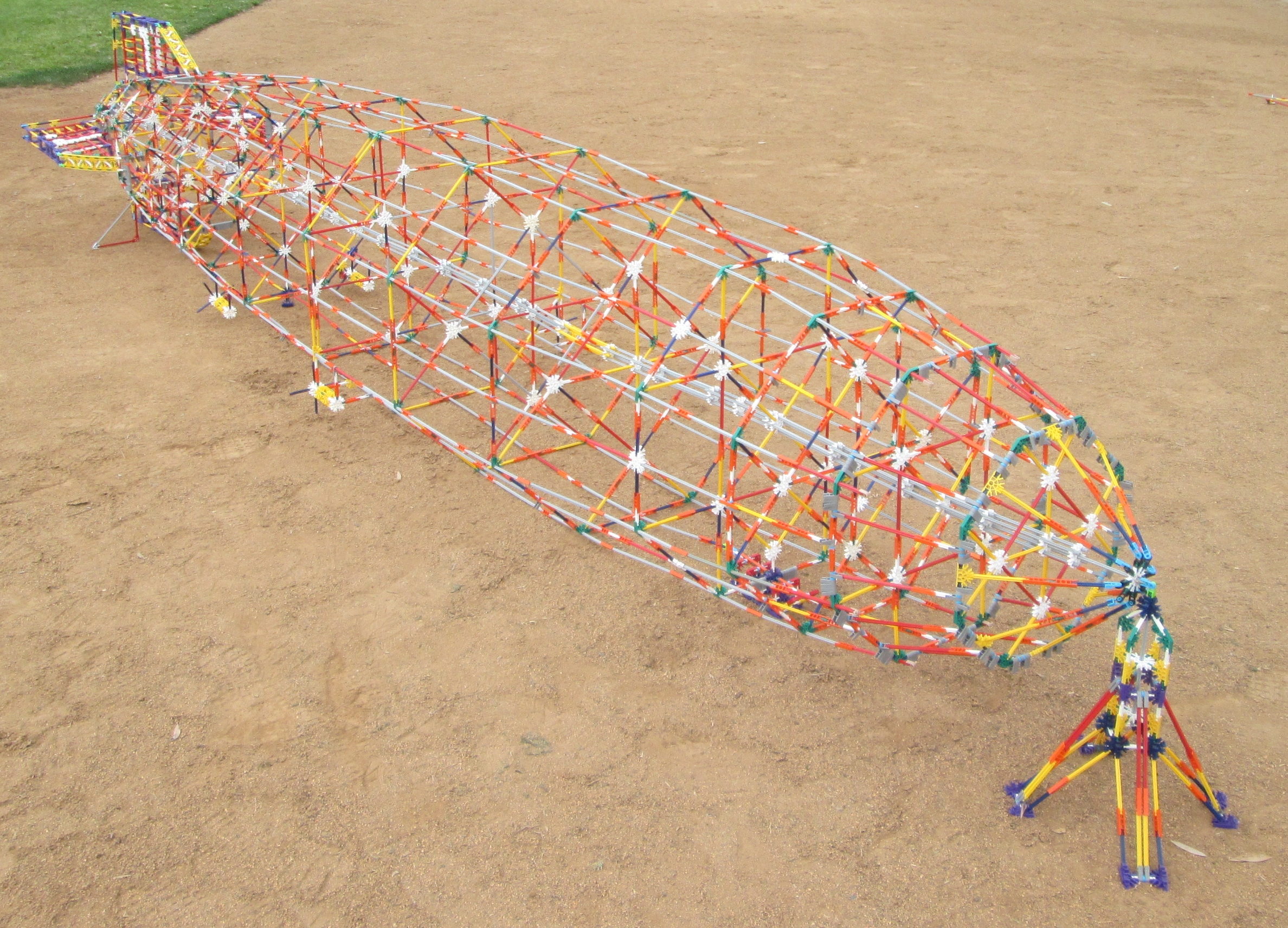
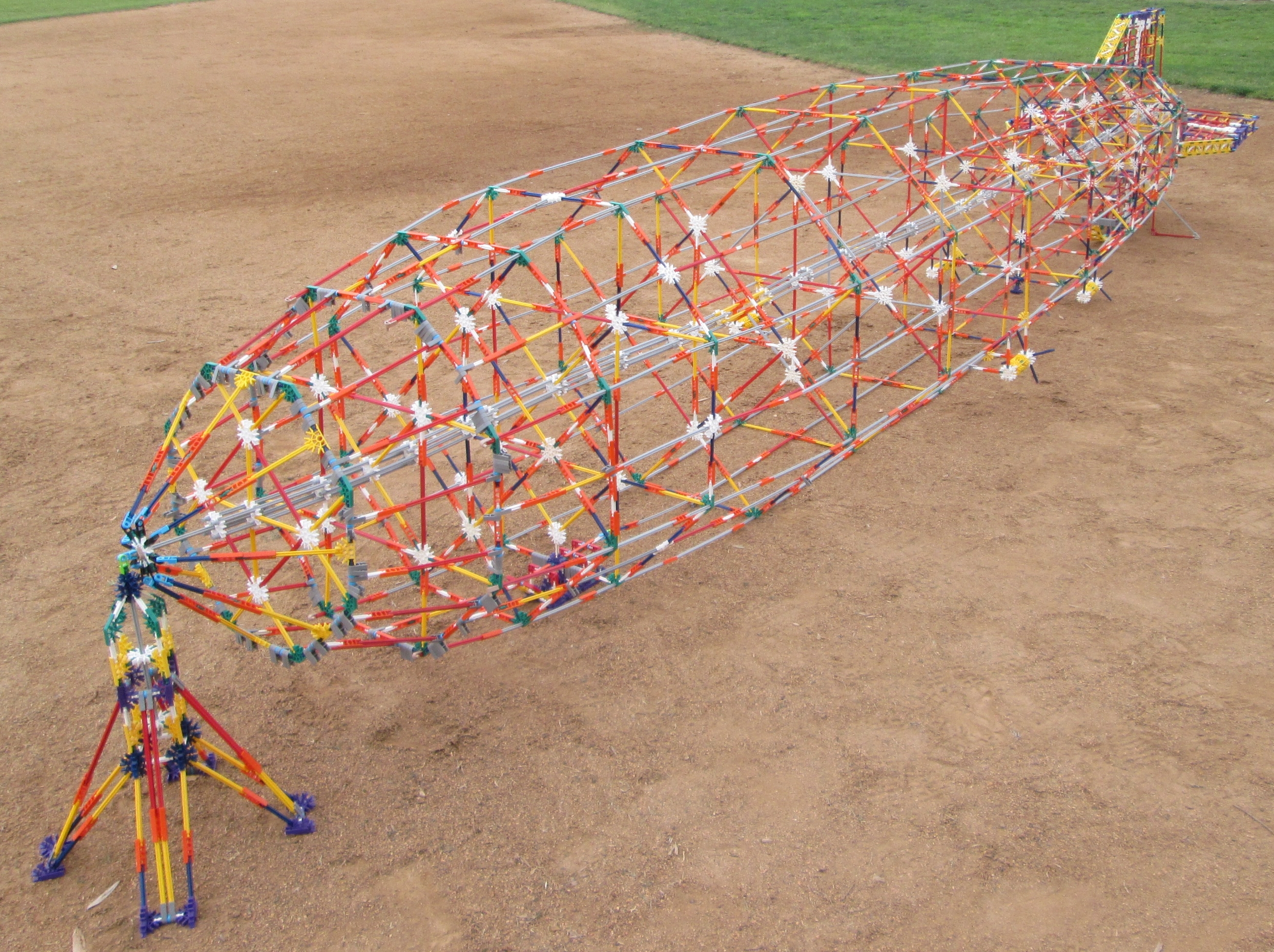
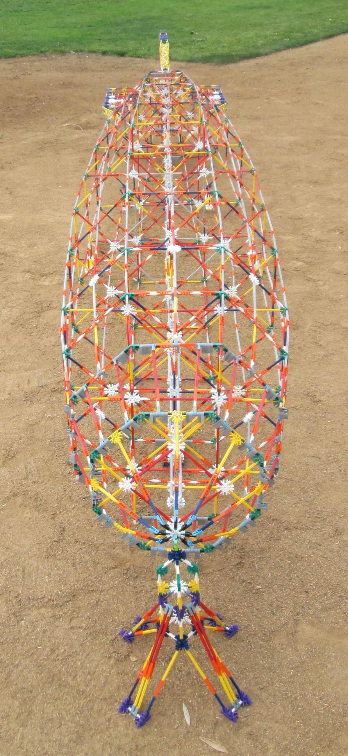
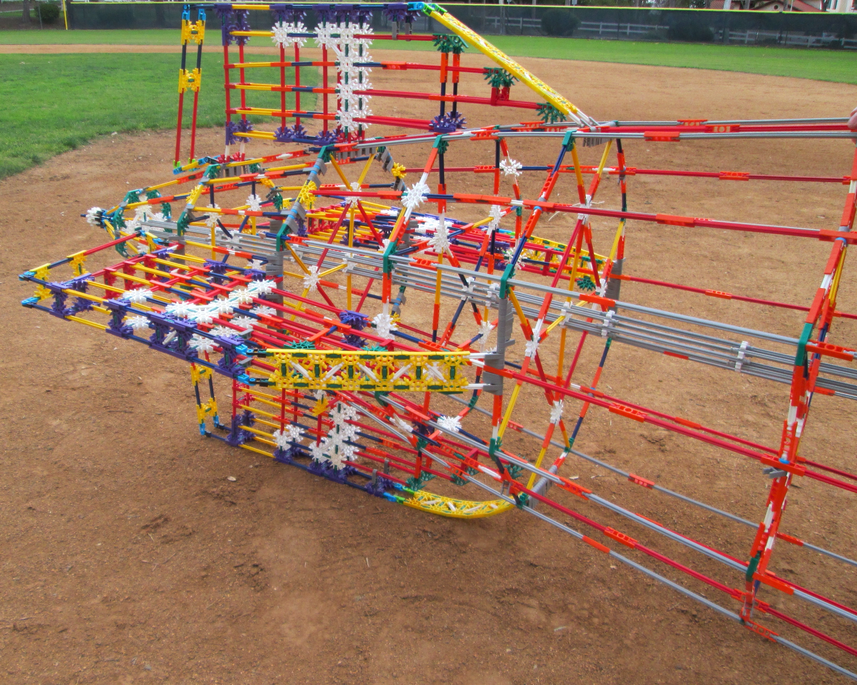
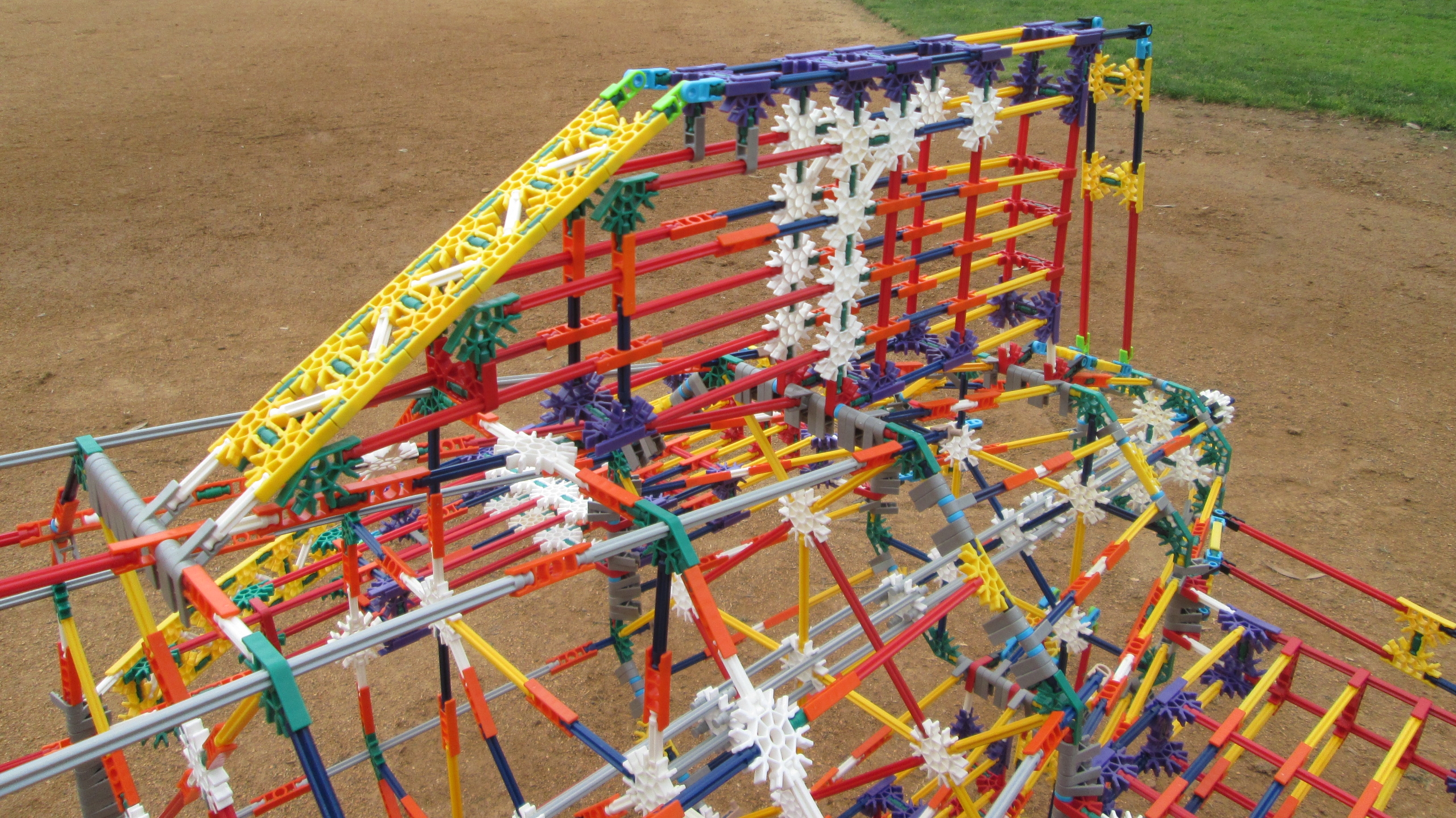
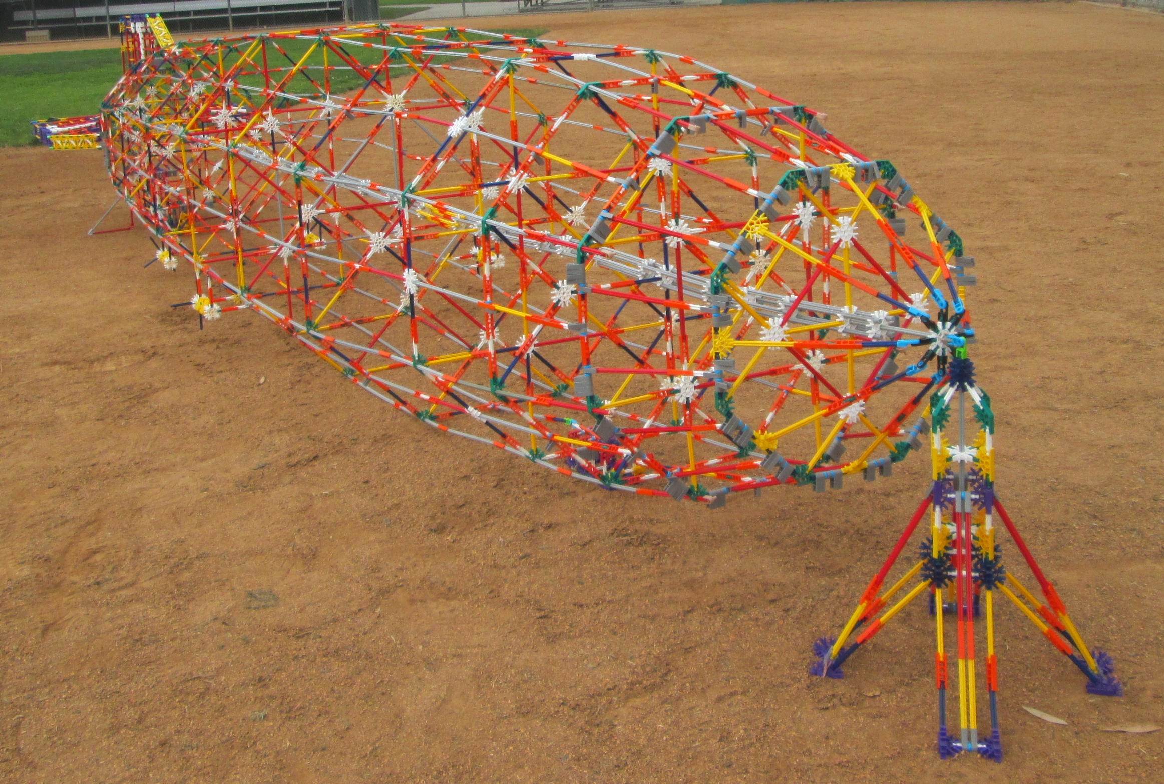
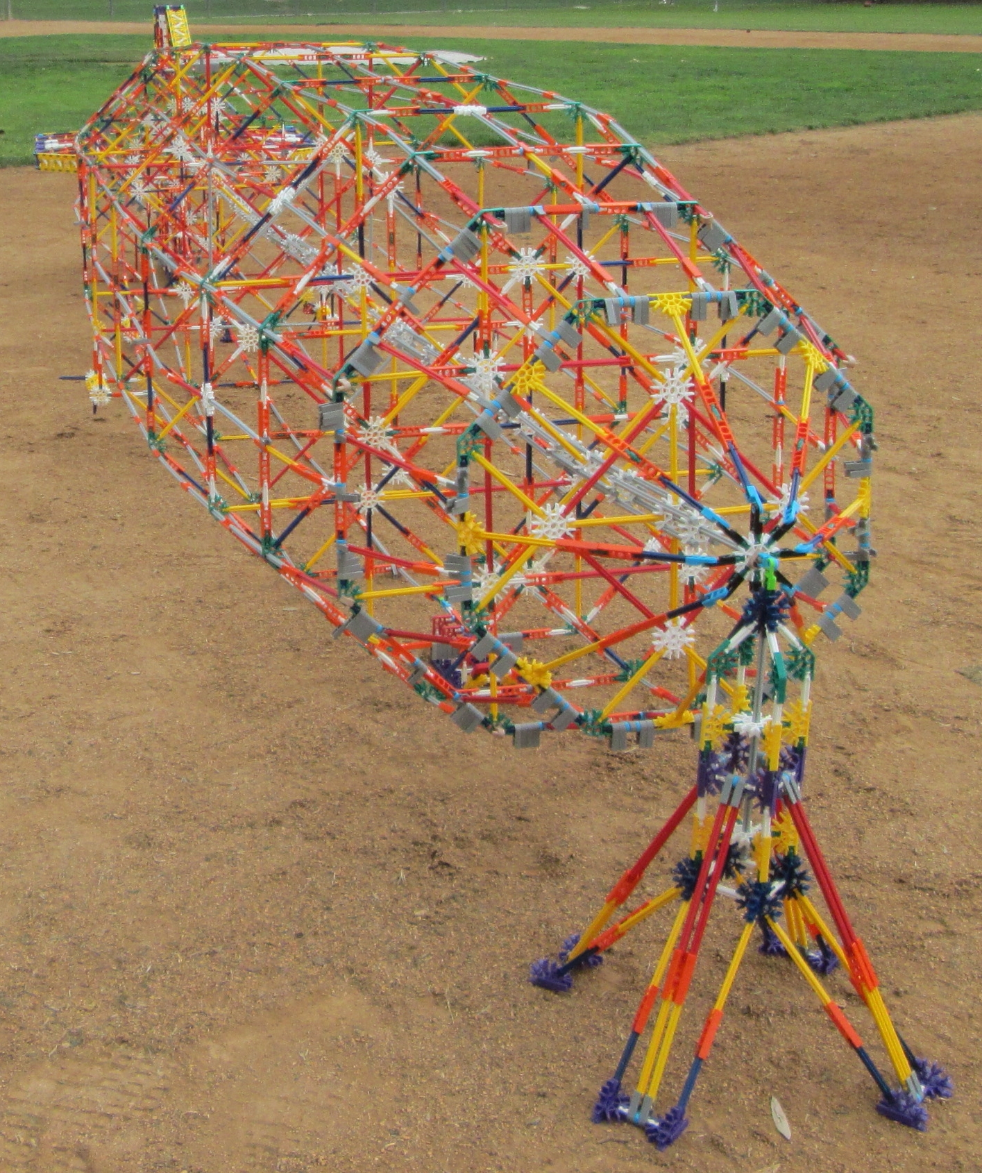
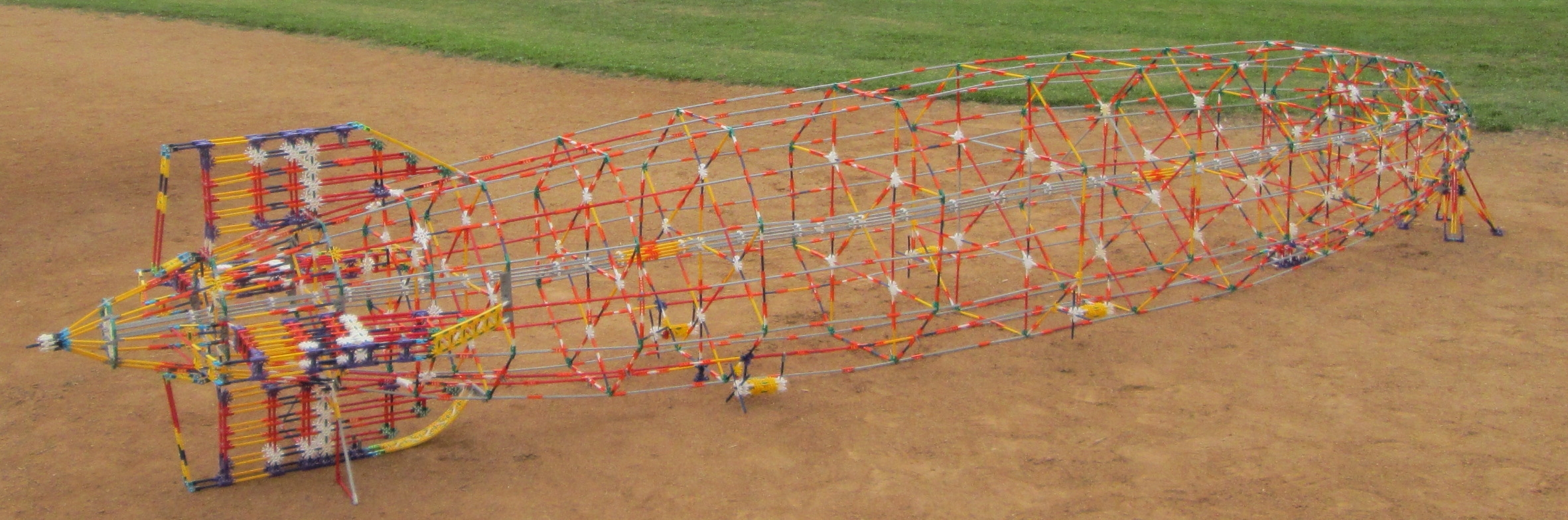
Here is a 1/54 scale model of the LZ 129 Hindenburg, the famous German zeppelin of the 1930's. This model of the airship is about 15 feet long and is made from nearly 5,000 K'NEX parts. Read on for more information on how this scale model was built. Click on the photos for larger versions.
|
|
TABLE 1

Horizontal    Vertical    Location
  pixel        pixel
coordinate   coordinate

      0           0       Extrapolated stern endpoint
     75          40
    195          98
    314         137
    434         172       Base of fin (excluding rudder)
    531         198
    628         222
    726         245       Frame 33.5
    823         266
    920         286
   1017         304
   1126         321       Fin leading edge join
   1234         337
   1342         352       Frame 62 (1st gas vent)
   1451         365
   1559         376
   1667         387
   1776         396
   1788         397
   1884         403
   1992         411       Frame 92 (2nd gas vent)
   2101         417
   2209         424
   2317         429
   2436         434
   2555         437
   2674         440       Frame 123.5 (3rd gas vent)
   2793         443
   2913         446
   3031         446
   3151         446
   3270         446
   3388         446       Frame 156.5 (4th gas vent)
   3508         444
   3603         442
   3627         441
   3746         437
   3854         432
   3963         427
   4070         421       Frame 188 (5th gas vent)
   4179         414
   4288         405
   4395         394
   4504         380
   4612         363
   4720         342       Frame 218 (6th gas vent)
   4829         317
   4937         285
   5045         242
   5132         199
   5219         140
   5294          64       Frame 244.5
   5329          18
   5344           0       Nosecone
In this scale, the airship has a length of 5344 pixels and a maximum diameter of 2 x 446 = 892 pixels, and so
it is almost exactly 6 times as long as its maximum diameter. These proportions are corroborated by the
dimensions of the actual Hindenburg airship: length 804 feet and diameter 135 feet. A diagram of these data
points serves to confirm the general shape of the airship profile (stern on the left):
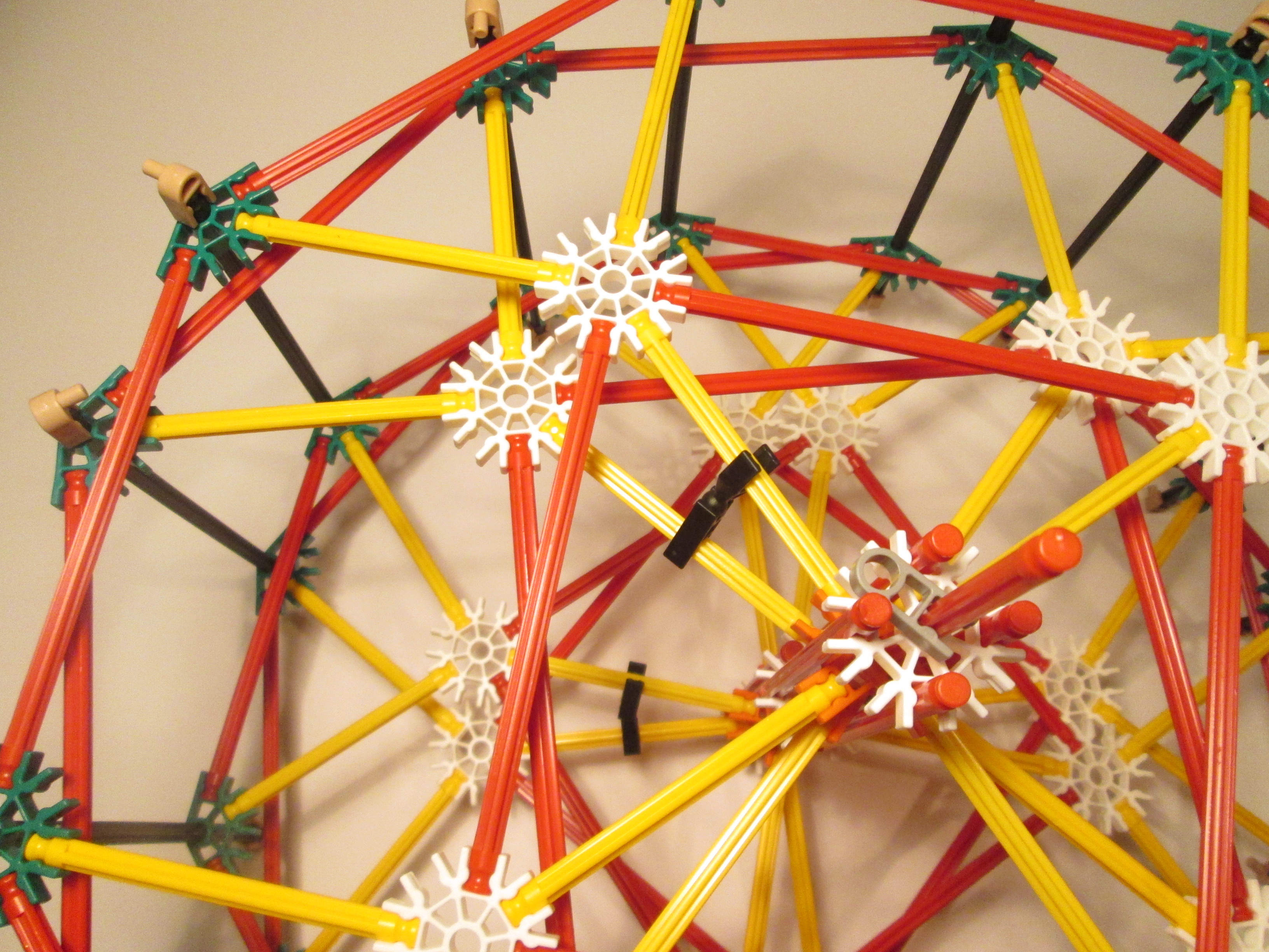
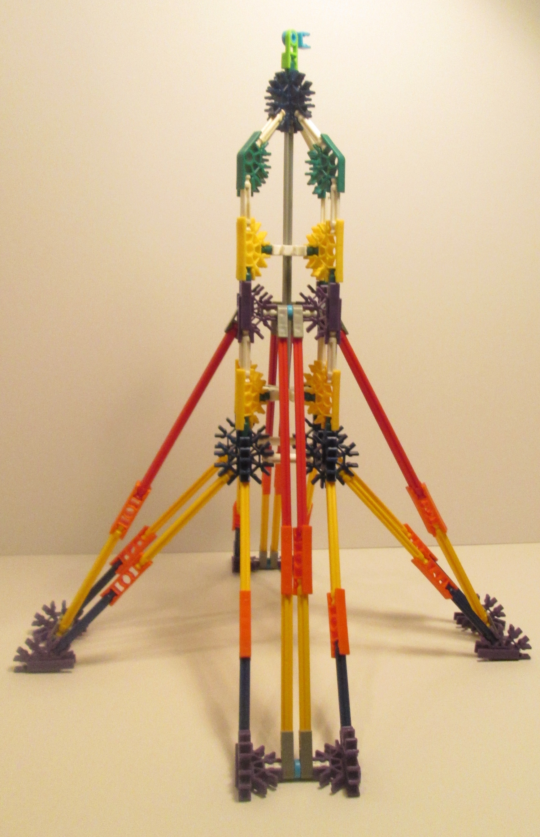
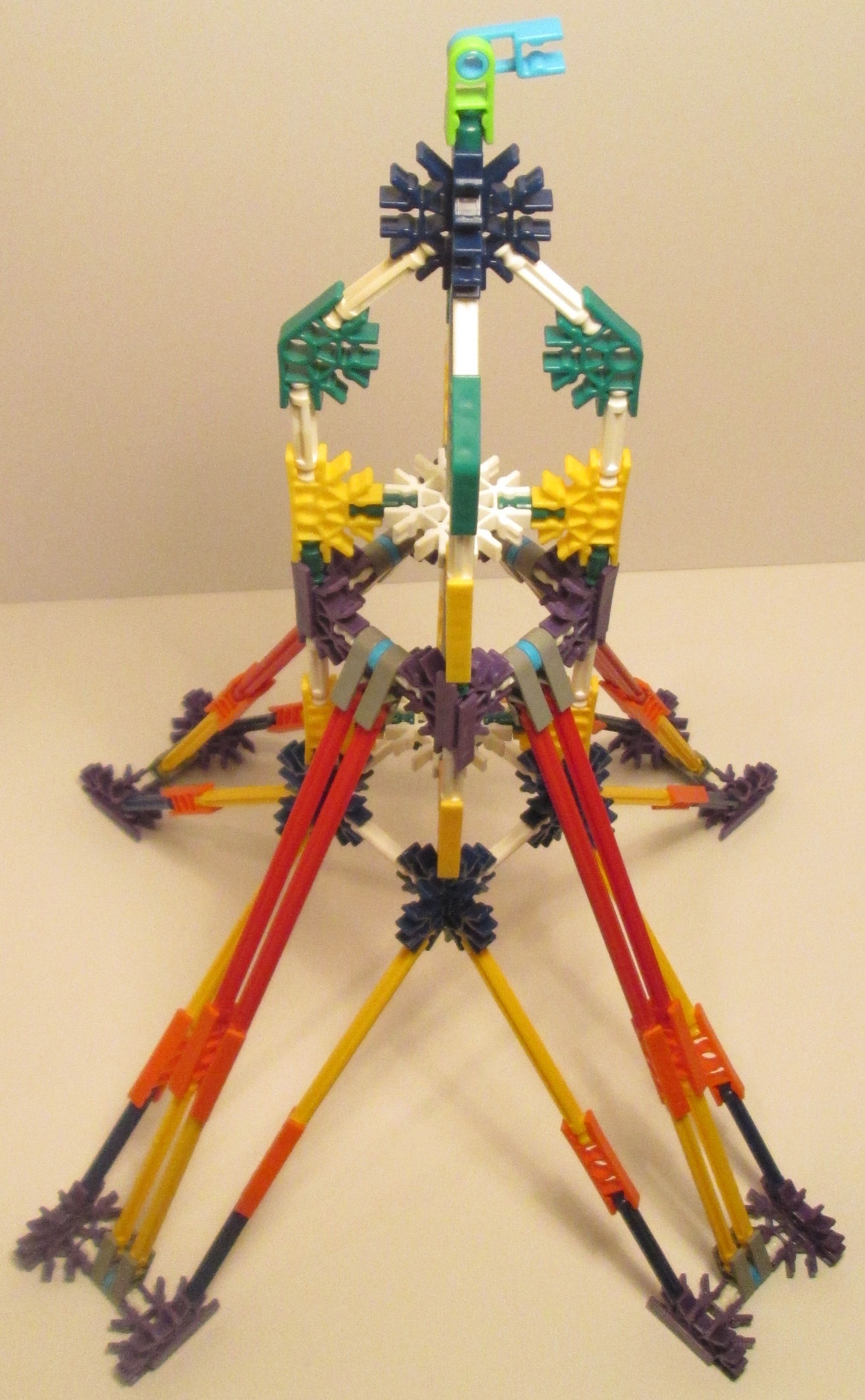
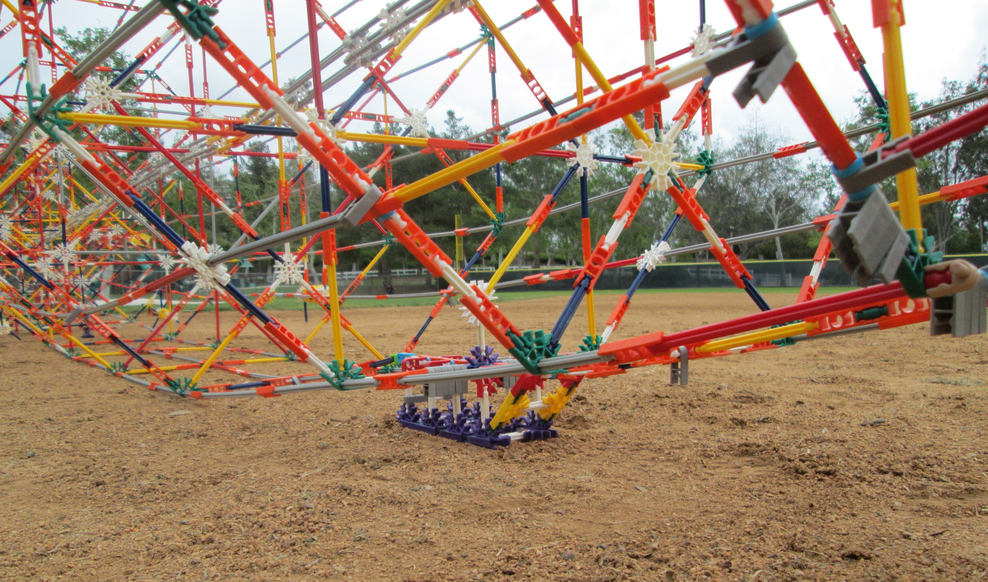
The cross-section of the actual zeppelin was a 36-sided regular polygon, but there are only a few possibilities for that shape in K'NEX without extensive bending of parts, particularly at smaller diameters. So we first tried a simpler 16-sided regular polygon (hexadecagon), and one way of creating it is to use two nested octagons with an offset of 22.5 degrees held in place with a ball-and-socket joint from one of the K'NEX figures:
|
|
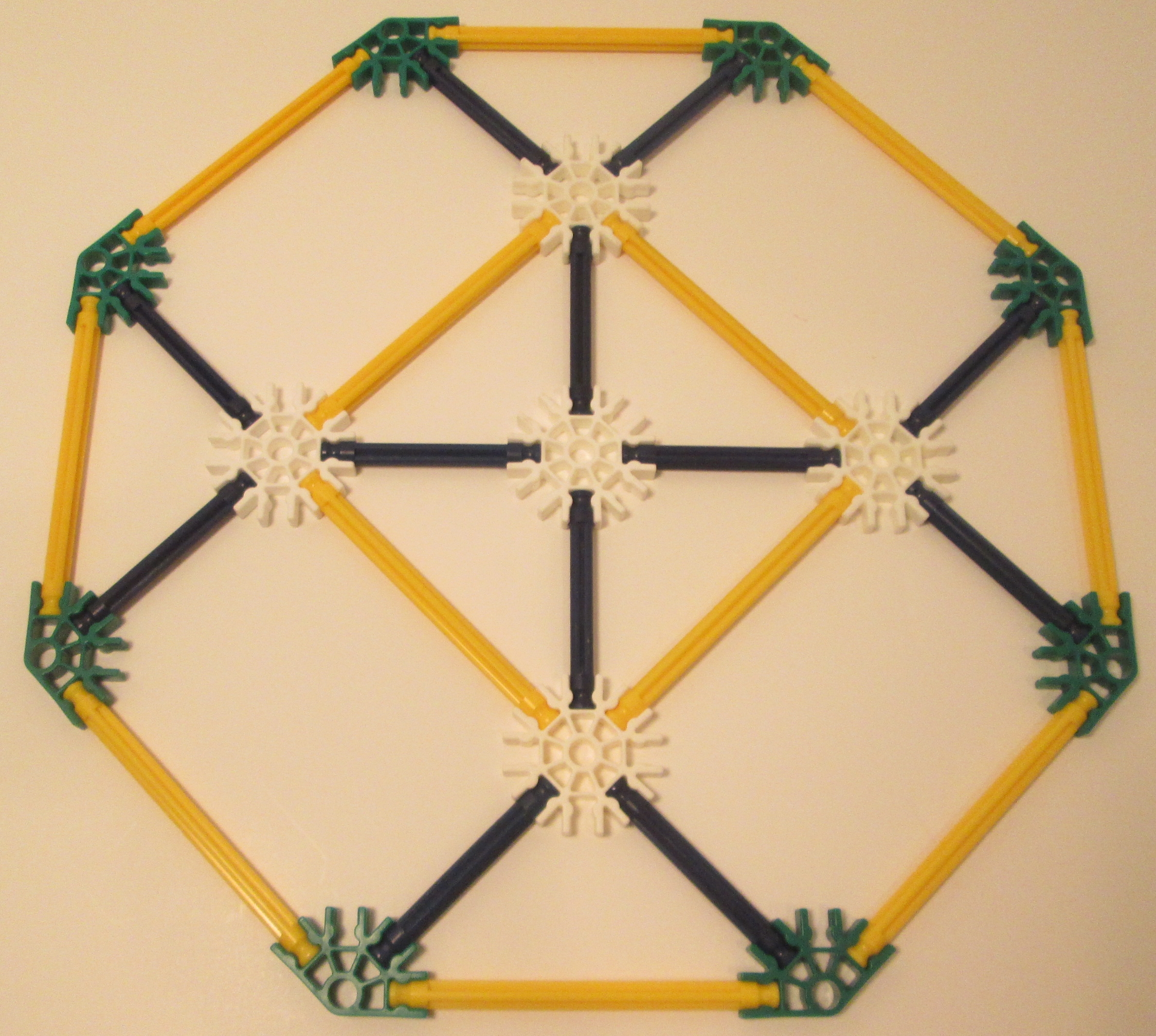
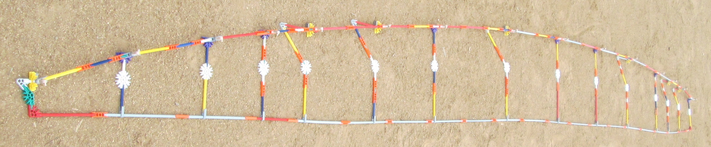
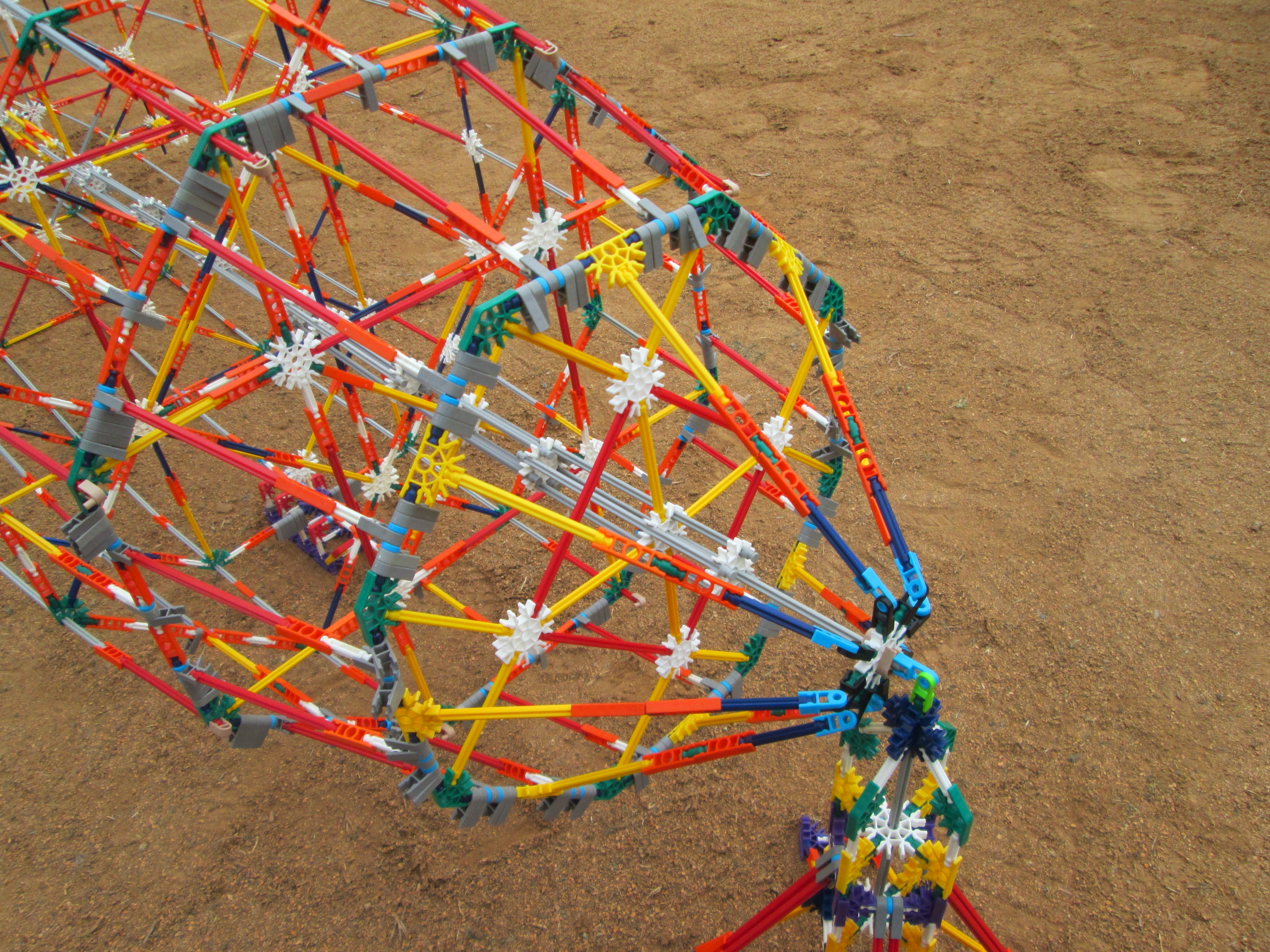
| However, this design proved to be unstable and irregular, and also had some challenges with attachment to the central axis using orange connectors. Instead, a sturdier solution is based on simple octagons with dual longitudinal stringers included on each of its sides, for a total of 16 longitudinal links between each vertical frame. While not as accurate as the actual zeppelin geometry, its overall shape and general appearance are achieved, as can be seen in the image at right. |
|
|
|
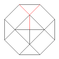
Each side of the octagon is equivalent to a number g of green rods plus a number W of white rods, all linked by connectors (usually orange ones). For example, if the side of the octagon is a red rod connected with a yellow rod, the overall side length can be represented as g = 4 & W = 2. This is because a red rod is equivalent to four connected green rods, and a yellow rod is equivalent to two connected white rods. The octagon side must use an even value for g so that diagonal Y-shaped bracing can be provided as shown in red in the diagram above. The overall length S (in millimeters) of the octagon side between the centers of the holes of the connectors used for the vertices is
S = 37.6 g + 53.2 W mmusing known dimensions for the K'NEX parts.
What is the radius R (half the diameter) of an octagon created in this way? It is the distance from its center to one of its vertices, as shown in red in the diagram below:
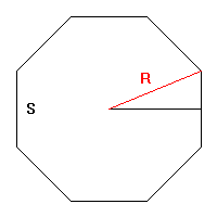
Since the interior angle of an octagon is 360/8 = 45 degrees, a right triangle can be visualized that has a central angle of 22.5 degrees and a height equal to one-half the octagon side S. Using a well-known formula from trigonometry, we have
R sin 22.5� = S/2or
R = 1.3066 STo provide enough detail for the airship appendages (engines, control car, etc.), the overall length of the model is 15 feet, or about a 1/54 scale with respect to the actual zeppelin. At the 6:1 aspect ratio described above, that scale results in a maximum diameter of 30 inches, or a maximum radius of 381 mm (at 25.4 mm per inch). Using the formula above and the previously-described requirement that the number g of green rods be even, we have 15 possibilities for the size of the vertical frames:
TABLE 2

----Frame side----   Radius

0 g   1 W    53 mm    70 mm
2 g   0 W    75 mm    98 mm
0 g   2 W   106 mm   139 mm
2 g   1 W   128 mm   168 mm
4 g   0 W   150 mm   197 mm
0 g   3 W   159 mm   209 mm
2 g   2 W   181 mm   237 mm
4 g   1 W   203 mm   266 mm
0 g   4 W   212 mm   278 mm
6 g   0 W   225 mm   295 mm
2 g   3 W   234 mm   307 mm
4 g   2 W   256 mm   336 mm
0 g   5 W   266 mm   348 mm
6 g   1 W   278 mm   364 mm
2 g   4 W   288 mm   376 mm
The first pass of the optimization process produces the following raw data, ordered from stern to bow:
TABLE 3

Frame    Slant distance   Error
side     to next frame

 53 mm        78 mm       -3 mm
 75 mm       140 mm        3 mm

106 mm       111 mm        2 mm
128 mm       123 mm        5 mm

150 mm        53 mm        0 mm
159 mm       135 mm       -6 mm

181 mm       167 mm        0 mm

203 mm        80 mm       -5 mm
212 mm       121 mm        7 mm
225 mm        99 mm        7 mm

234 mm       312 mm       -2 mm

256 mm       179 mm        2 mm
266 mm       303 mm       -1 mm

278 mm       447 mm        0 mm

288 mm       400 mm        0 mm

288 mm       397 mm       -2 mm

278 mm       283 mm       -3 mm
266 mm       133 mm       -4 mm

256 mm       216 mm       -3 mm

234 mm        64 mm      -10 mm
225 mm        81 mm       -5 mm
212 mm        52 mm        0 mm

203 mm        99 mm        7 mm
181 mm        76 mm        0 mm
159 mm        29 mm        8 mm

150 mm        65 mm        9 mm
128 mm        52 mm        1 mm
106 mm        65 mm       10 mm
 75 mm        39 mm       -1 mm
 53 mm
Table 3 lists the slant distances between frames if all of the possible K'NEX frame sizes were used for both bow and stern tapers of the airship. It also shows the errors resulting from the approximations of the actual slant distances with K'NEX parts. To avoid overcrowded frames and retain an accurate airship shape, the goal is to find optimal frames that are at least 8 inches (203 mm) apart, about the length of a grey K'NEX rod. This has the advantage of reducing error in the slant distances since they will be computed over a longer distance. Also, we want to ensure that frames close to the leading and trailing edges of the tail fins are included so that we have good attachment points. Those fin-attachment frames are:
TABLE 4

Horizontal    Vertical    Vertical   K'NEX    K'NEX    Location
coordinate   coordinate   distance   radius    side

  434 px       172 px      145 mm    139 mm   106 mm   Base of fin (excluding rudder)
 1126 px       321 px      271 mm    266 mm   203 mm   Fin leading edge join
There may be additional, intermediate frames that can also be used to anchor the fins.
Based on a manual analysis of the raw data in Table 3, optimal selections are grouped together to produce the following smaller list of frames and more-accurate slant distances:
TABLE 5

Frame    ---Slant distance---   Error
 side       to next frame

 53 mm   218 mm    3 g    2 W    1 mm
106 mm   233 mm    2 g    3 W    1 mm	Fin attachment point
150 mm   189 mm    5 g    0 W   -1 mm
181 mm   167 mm    3 g    1 W    0 mm
203 mm   300 mm    8 g    0 W    0 mm	Fin attachment point
234 mm   312 mm    4 g    3 W   -2 mm
256 mm   482 mm   10 g    2 W    0 mm
278 mm   447 mm    2 g    7 W    0 mm
288 mm   400 mm    5 g    4 W    0 mm
288 mm   397 mm    2 g    6 W   -2 mm
278 mm   416 mm    4 g    5 W    0 mm
256 mm   216 mm    0 g    4 W   -3 mm
234 mm   197 mm    1 g    3 W    0 mm
203 mm   204 mm    4 g    1 W    0 mm
150 mm   220 mm    3 g    2 W   -1 mm
Table 5 coincidentally contains 15 optimal frames, but is not related to the 15 possible K'NEX frame sizes in Table 2 since some frame sizes are reused at each end of the airship, and other sizes are not used at all. A diagram of these data points serves to confirm the general shape of the airship (the nose and stern cones will be fitted manually):
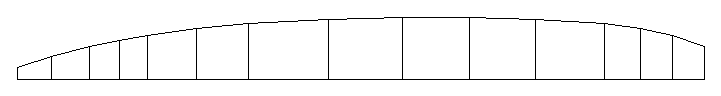
TABLE 6 Frame side Diagonal bracing Slant distance to next frame Radius Slant Deviation from 180� W g Y+B+g 70 mm 218 mm * Y B Y+B+W 139 mm 233 mm 4 * R Y R+g 197 mm 189 mm 2 * Y+B B+W B+W+g 237 mm 167 mm 2 R+W Y+g 2R 266 mm 300 mm 2 Y+B+W B+W+g R+Y+W 307 mm 312 mm 3 R+Y Y+B 2R+Y+B 336 mm 482 mm 2 R+B+W Y+W+g G+Y+B+W 364 mm 447 mm 2 G+B R+W G+R+g 376 mm 400 mm 2 G+B R+W G+Y+B 376 mm 397 mm 2 R+B+W Y+W+g G+R+W 364 mm 416 mm 2 R+Y Y+B G 336 mm 216 mm 4 Y+B+W B+W+g Y+W+g 307 mm 197 mm 4 R+W Y+g R+W 266 mm 204 mm 8 * R Y Y+B+g 197 mm 220 mm *where the following symbols are used:
	g: Green rod
	W: White rod
	B: Blue rod
	Y: Yellow rod
	R: Red rod
	G: Grey rod
	+: Orange connector
The rods in the diagonal bracing are one K'NEX size down from those in the frame side. Table 6 also includes calculations for how closely to a straight angle (180�) the longitudinal stringers intersect the perimeters of the vertical frames. For example, in the side-view profile below, the frame with one yellow rod for each side (radius 139 mm) has the following dimensions (mm), with respect to its two adjacent frames:
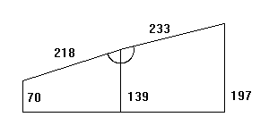
These dimensions result in a calculation of 176� for the indicated angle, or about 4� off of a straight angle, using the inverse-cosine trigonometric function:
139 - 70 139 - 197 Arccos ---------- + Arccos ----------- = 176� 218 233As described above, the zeppelin model has 16 stringers connected to the perimeter of each octagonal frame. For the best uniform appearance, these stringers pass through the corners of the octagons, as well as through the midpoints of their sides. The corner stringers pass through the central hole of each green connector used for the frame corner. In practice, depending on the stringer lengths involved, a deviation of more than about 4� or so from a straight 180� intersection angle results in too much tilting of the green connector and associated distortion of the vertical frame and/or stringers. Therefore, the stringer connections at the frames indicated with asterisks in Table 6 (along with the nose and tail cones) have pivoting attachments to allow for steeper angles between frames.
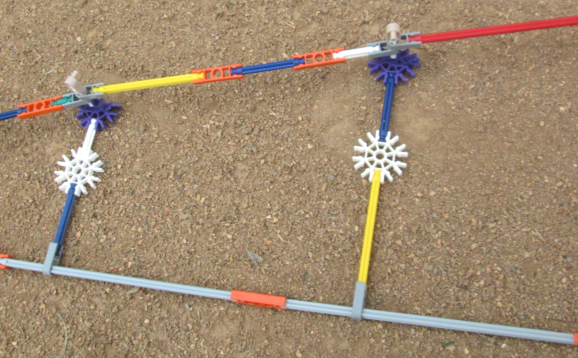
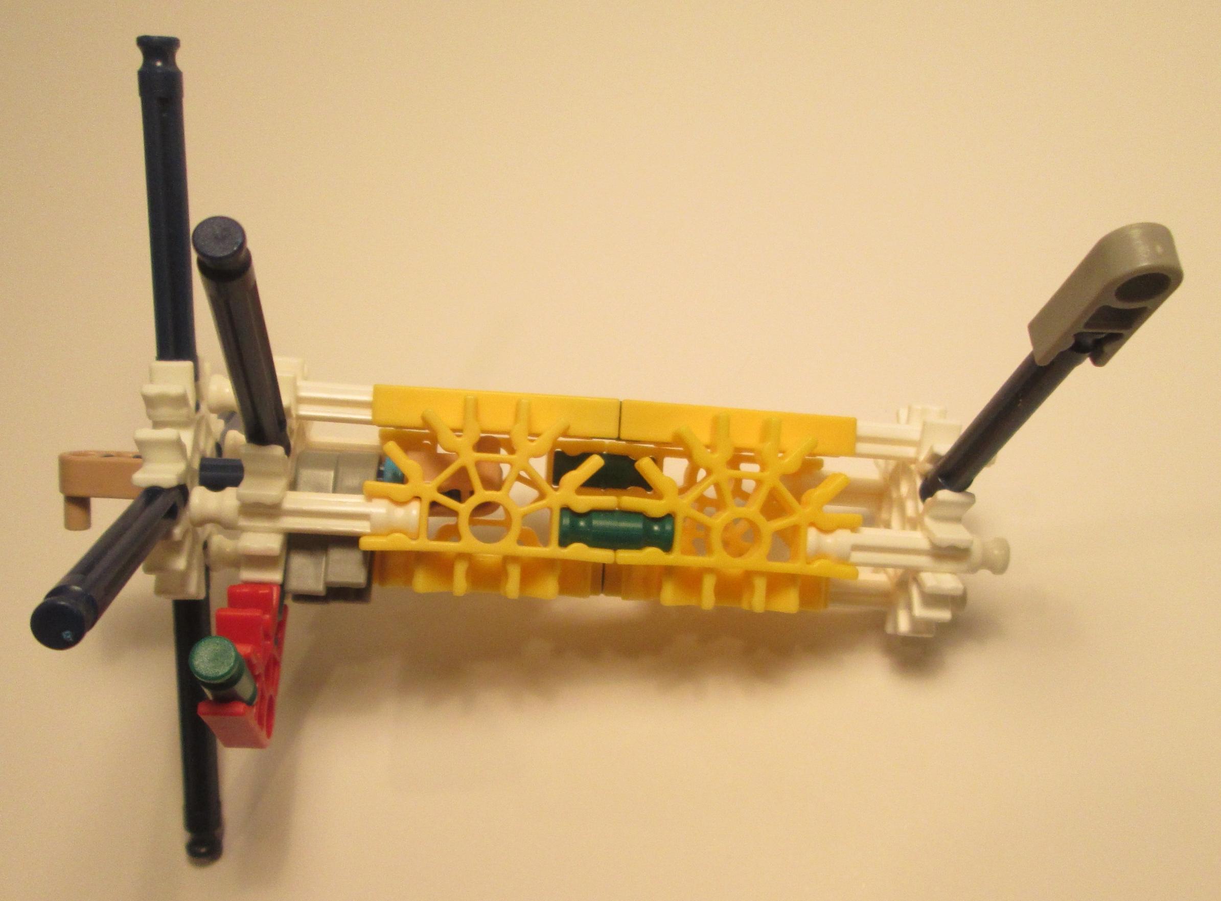
At those locations needing flexible angles between consecutive frames, stringers are attached to the frame perimeter with pivots. These pivots can be realized with dark-grey K'NEX connectors that attach to the end of stringer rods and swing freely on the octagon sides. Multiple pivots may be needed on each side, depending on the number of fore and aft stringer connections.
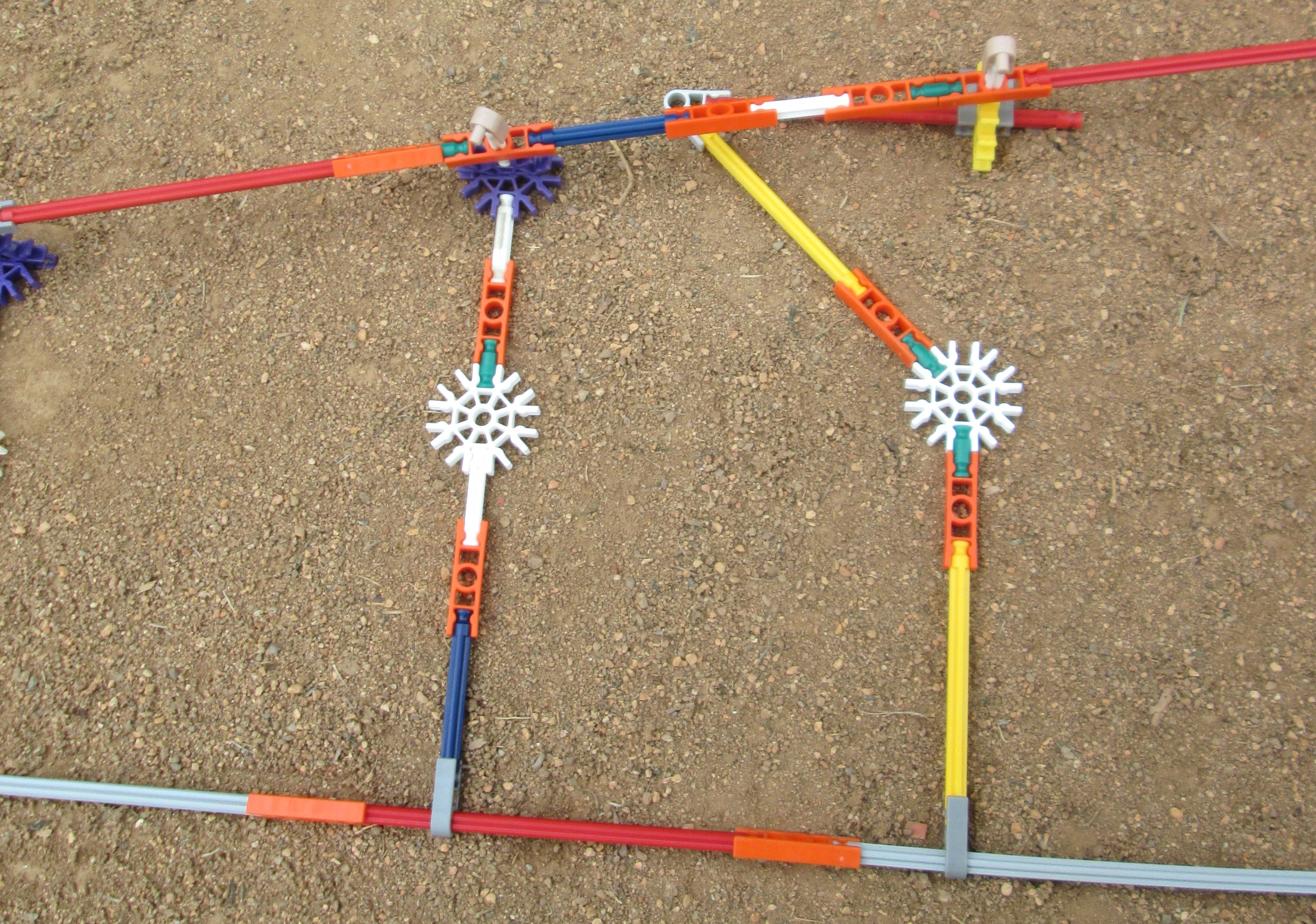
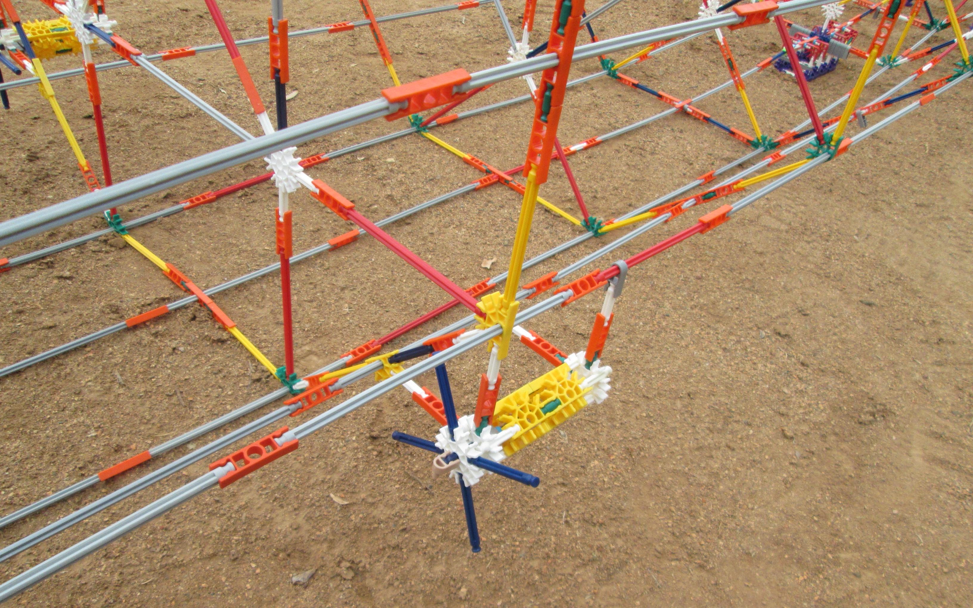
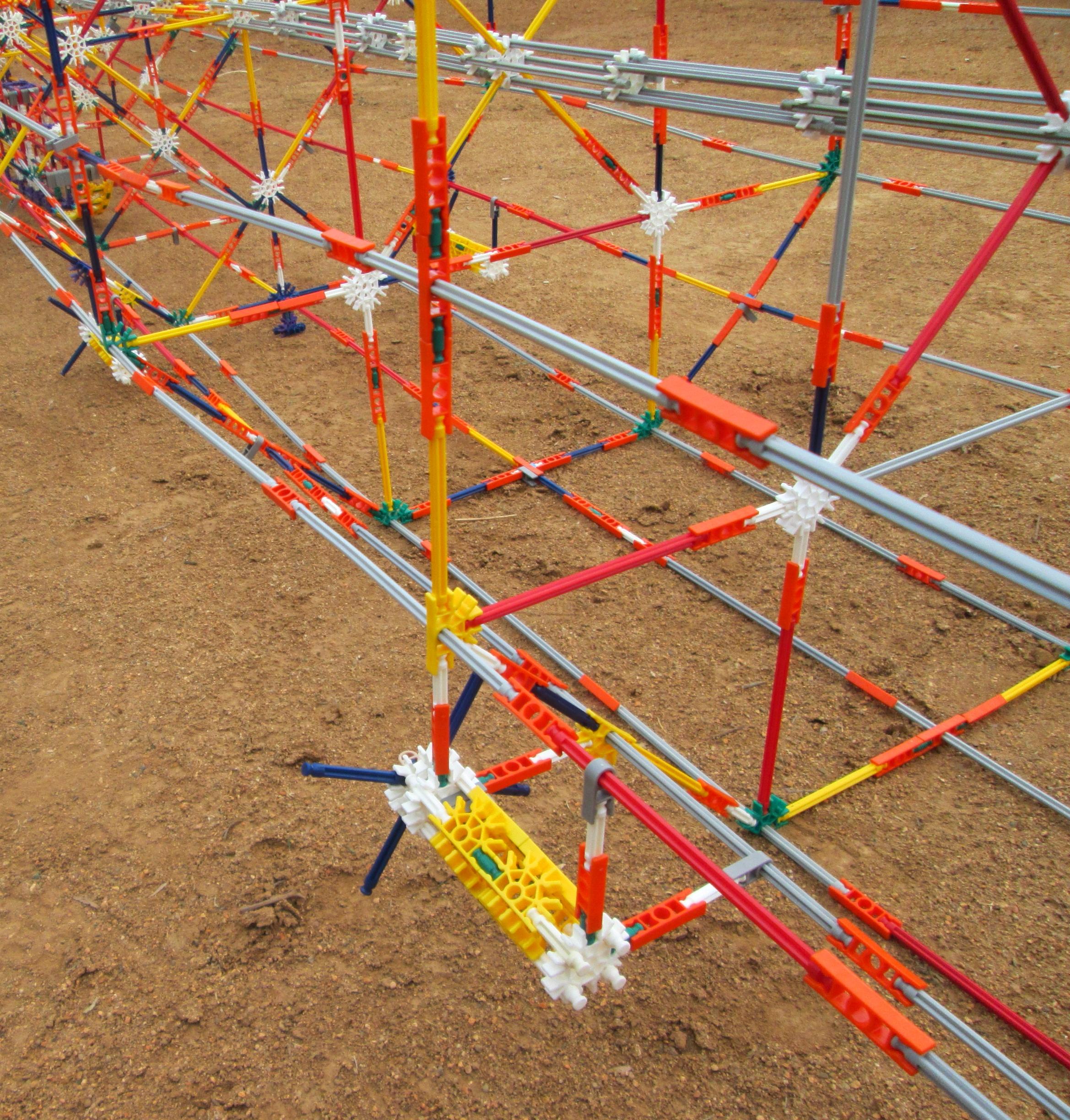
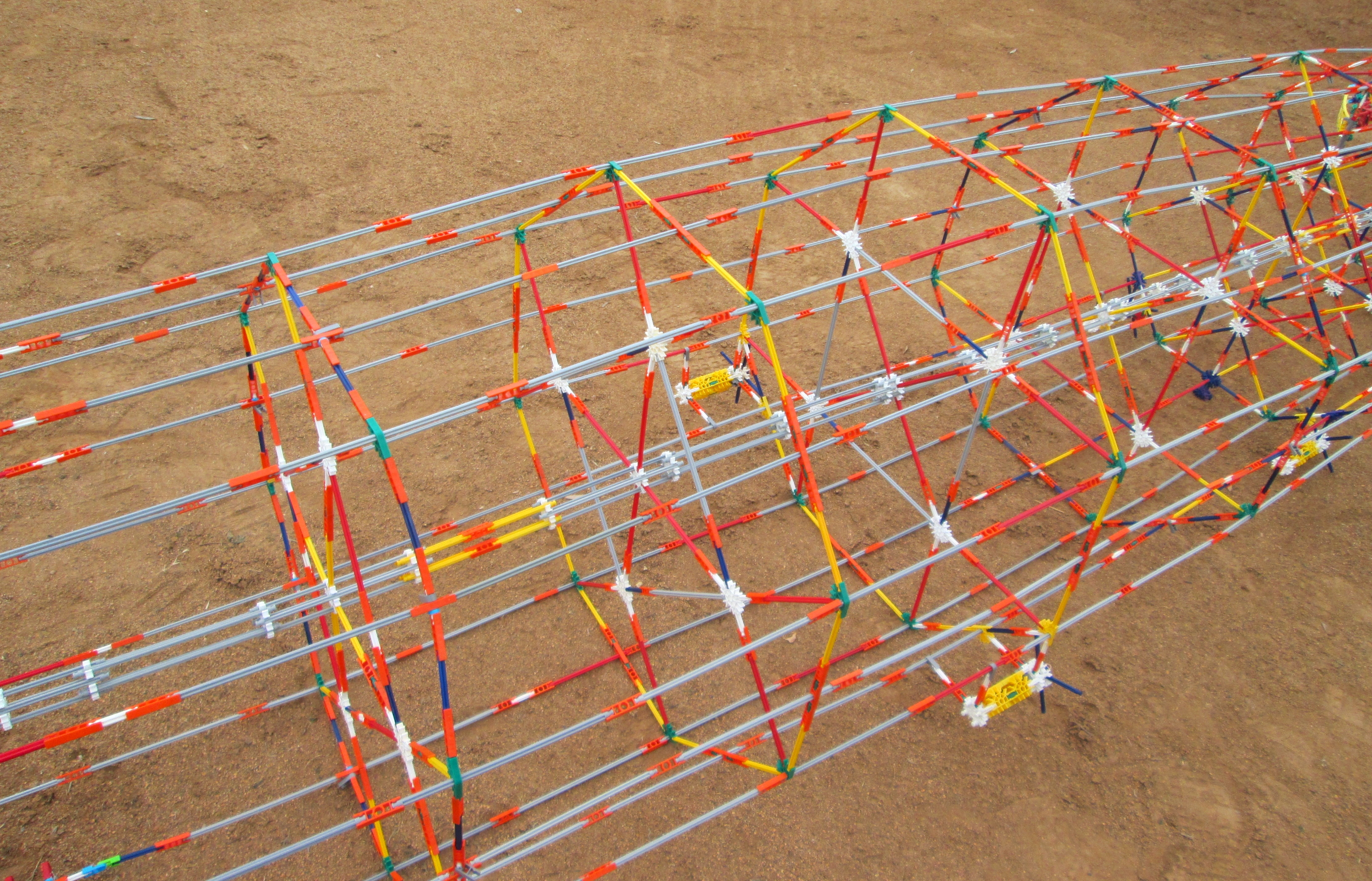
In Table 6, frames not terminated with an asterisk at the end of the line are located where there isn't much tapering in the airship envelope, and so stringer pivots do not not need to be used on them. In this case, the stringer rods between the frames can be rigidly attached to connectors on the frame structure. This design is shown in the right-hand profile photo below, while the left-hand photo shows the pivots used when stringers make a slight corner at the frame:
|
|
Starting at the stern and moving forward, a frame construction plan is as follows:
TABLE 7

Frame side     Implementation   Pattern                                    Photo            Notes

W              W                XX|                                        Frame style A
Y              W+W              CX|(YYYY)|XC                               Frame style B
Y (at fin)     Y                CXFCCXCCFXC                                Frame style Bf
R              B+B              CC|X|CC(YYYY)CC|X|CC                       Frame style C    Start of stringers at octagon corners
R (at fin)     R                CCXCC|FCCXCCF|CCXCC                        Frame style Cf   Start of stringers at octagon corners
Y+B            g+W+W+g          (OOOO)..:(WWWW):..(OOOO)                   Frame style D
R+W            B+W+B            (BBBB)(OOOO)|OC(OOOO)(BBBB)                Frame style E
R+W (at fin)   R+W              CCCCCCCCCCFCCOCCFC(OOOO):..                Frame style Ef
Y+B+W          g+W+W+W+g        (OOOO)..:(OOOO)|OC(OOOO):..(OOOO)          Frame style F
R+Y            W+B+B+W          ..:(OOOO)(BBBB)(OOOO)(BBBB)(OOOO):..       Frame style G    Stringer passthrough at midpoint
R+B+W          g+B+W+B+g        (OOOO)(BBBB)(OOOO)|OC(OOOO)(BBBB)(OOOO)    Frame style H
G+B            Y+g+g+Y          (YYYYYYYYY)(OOOO)(OOOO)(OOOO)(YYYYYYYYY)   Frame style I    Stringer passthrough at midpoint
G+B            Y+g+g+Y          (YYYYYYYYY)(OOOO)(OOOO)(OOOO)(YYYYYYYYY)   Frame style I    Stringer passthrough at midpoint
R+B+W          g+B+W+B+g        (OOOO)(BBBB)(OOOO)|OC(OOOO)(BBBB)(OOOO)    Frame style H
R+Y            W+B+B+W          ..:(OOOO)(BBBB)(WWWW)(BBBB)(OOOO):..       Frame style J
Y+B+W          g+W+W+W+g        (OOOO)..:(OOOO)|OC(OOOO):..(OOOO)          Frame style F
R+W            B+W+B            CCCC|X|(OOOO)|XC(OOOO)|X|CCCC              Frame style K    End of stringers at octagon corners
R              B+B              CC|X|CC(YYYY)CC|X|CC                       Frame style L
where the following notation is used:
	g: Green rod
	W: White rod (inline space for 2.5 connectors)
	B: Blue rod (inline space for 6 connectors)
	Y: Yellow rod (inline space for 11 connectors)
	R: Red rod (inline space for 18 connectors)
	G: Grey rod (inline space for 28 connectors)
	+: Orange connector inline (occupies space of 6 connectors)

	X: Dark-grey connector at end of stringer
	O: Orange connector at end of stringers
	F: Fin connector
	C: Dark-grey connector as spacer (rotating freely)
	|: Light blue washer (1/2 connector thickness)
	.: Connector space on white rod
	:: Washer space on white rod
	(OOOO): Orange connector (connected inline with rods)
	(YYYY): Yellow connector
	(WWWW): White connector
	(BBBB): Blue rod
	(YYYYYYYYY): Yellow rod

With the aforementioned ratio of 1.186 pixels per mm, we can determine the K'NEX parts to approximate the fin profile:
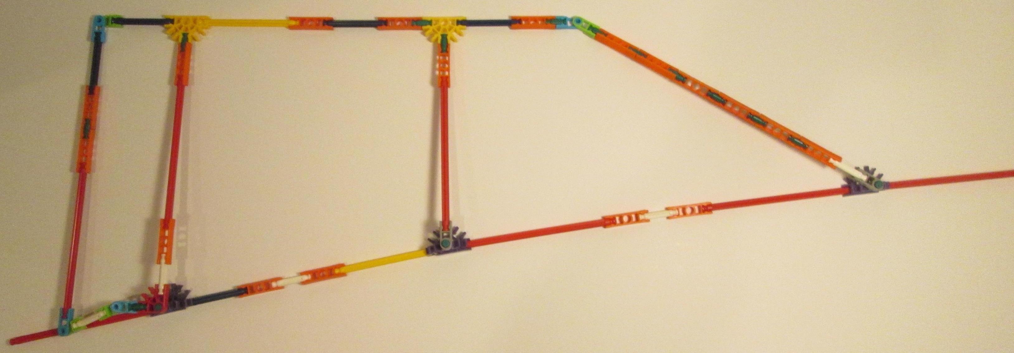
Based on the technical drawings referenced above, the maximum thickness of each fin is 89 pixels, or about 75 mm at the scale of the model. The average fin thickness is somewhere around half that, equivalent to two connectors attached by a single green rod. Therefore, two sides of each three-dimensional fin are created and connected together with a green rod. A total of three connections of each fin to the main body of the airship model are determined by fitting. Technically, the lower fin of the actual airship is slightly different from the other three in that it tapers upward slightly towards the stern. However, this minor change is not implemented in the K'NEX model, and all four of its fins are identical.
|

|
The following pictures highlight the connections of the fin to the airship envelope:
|
|
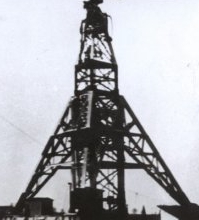
4g + W + (2g + 4W)/2 = 5g + 3W = 348 mm.This size provides a number of options for a realistic mast design. In particular, outer supporting struts at a steeper angle of about 60 degrees are possible, similar to the actual Lakehurst mooring mast. We ended up extending the height of the mooring mast by one additional green rod to facilitate the mast design and allow clearance for the control car.
|
|
|
|
|

|
|
And here are some close-ups of the control car:
|
|
A couple of small artificial props can be seen in some of the photos; these are added to prevent the model from sagging or tipping since its central axis is somewhat flexible.
|
|
|
|

|
A modification of the central axial tube can be used to allow the airship model to be easily disassembled into sections:
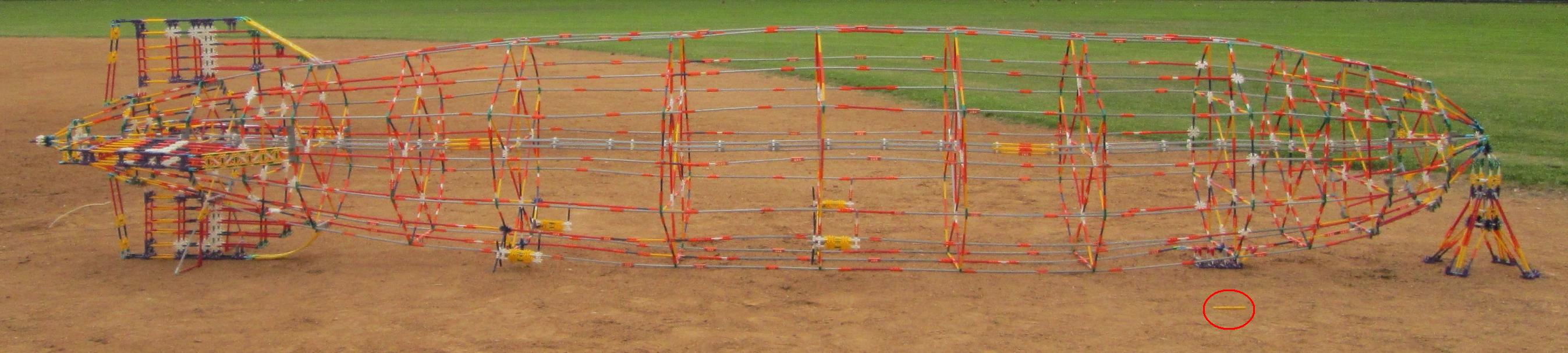
If the K'NEX airship were the actual size of the Hindenburg zeppelin, our 1/54 model would be the size of a yellow rod in comparison (outlined in red below):
HINDENBURG AIRSHIP PART COUNTS

Orange Connector        1007
Green Rod                622
Dark Grey Connector      500
White Rod                468
Blue Rod                 399
Yellow Rod               289
Grey Rod                 243
Red Rod                  227
Purple Connector         204
White Connector          184
Washer                   169
Green Connector          144
Yellow Connector         140
Red Connector             59
Hinge                     50
Brown Connector           29
Blue Connector            16
Light Grey Connector       2

Total                   4752